20+ tv receiver block diagram
LT201CB 201 LCD TV Receiver Block Diagram -1xls KTV Global KTV Global 201 LCD TV Receiver. The simplified block diagram of a black and white TV receiver Monochrome TV Receiver is shown in animation.

Block Diagram Of The Receive Path For The Ettus Research Wbx Rf Download Scientific Diagram
According to the Block Diagram of Black and White Television Sets In a typical black and white television receiver the signal from the antenna is fed to the tunerTwo channel selector.

. This arrangement was left out of Figure 17-9 for simplification but is shown in detail in figure 17-10. Figure shows a block diagram of an HDTV transmitter. DBS TV RECEIVER BLOCK DIAGRAM.
The block diagram can be broadly divided into two -sections viz an amplitude modulated transmitter and a frequency modulated transmitter. Former is used for video modulation. Block diagram of a colour TV receiver.
L The receiving antenna intercepts radiated RF signals and the tuner selects desired channels frequency band converts it to the common IF band of. FB824 MC44200Monitor Subsystem Multimode Color Monitor Processor Adaptable to 30 kHz to 64 kHz horizontal 45 to 100 Hz vertical. Image Rejection BPF BPF BPF BPF QPSK Demod Frequency Synthesizer Microprocessor De - Interlea ver Outer Decoder Digital Demux MPEG 2.
According to the Block Diagram of Black and White Television Sets In a typical black and white television receiver the signal from the antenna is fed to the tuner. The receiving antenna intercepts radiated RF si. A Color Television Receiver Block Diagram almost invariably has an AFC circuit as indicated in Figure 17-25.
The design is shown in block diagram form in Figure 7 below. It will definitely ease you to look guide block diagram of colour tv receiver ppt pdf as you such as. According to the Block Diagram of Black and White Television Sets In a typical black and white television receiver the signal from the antenna is fed to the tuner.
A modern television Monochrome Television Receiver Block Diagram has two tuners. The video from the camera consists of the R G and B signals that are converted to the luminance and. FCC ID KTV Global Corporation LT201CB Block Diagram.
Thus active imaging can greatly. The bridge rectifier conducts only its vbi into circular polarization the master antenna or a dbs tv receiver block diagram which supply. Slope of 5910 -13 determined from these data corresponds to the nominal frequency offset.
By searching the title publisher or authors of guide you truly want you can discover them. It is often called automatic fine tuning AFT and is used automatically to.

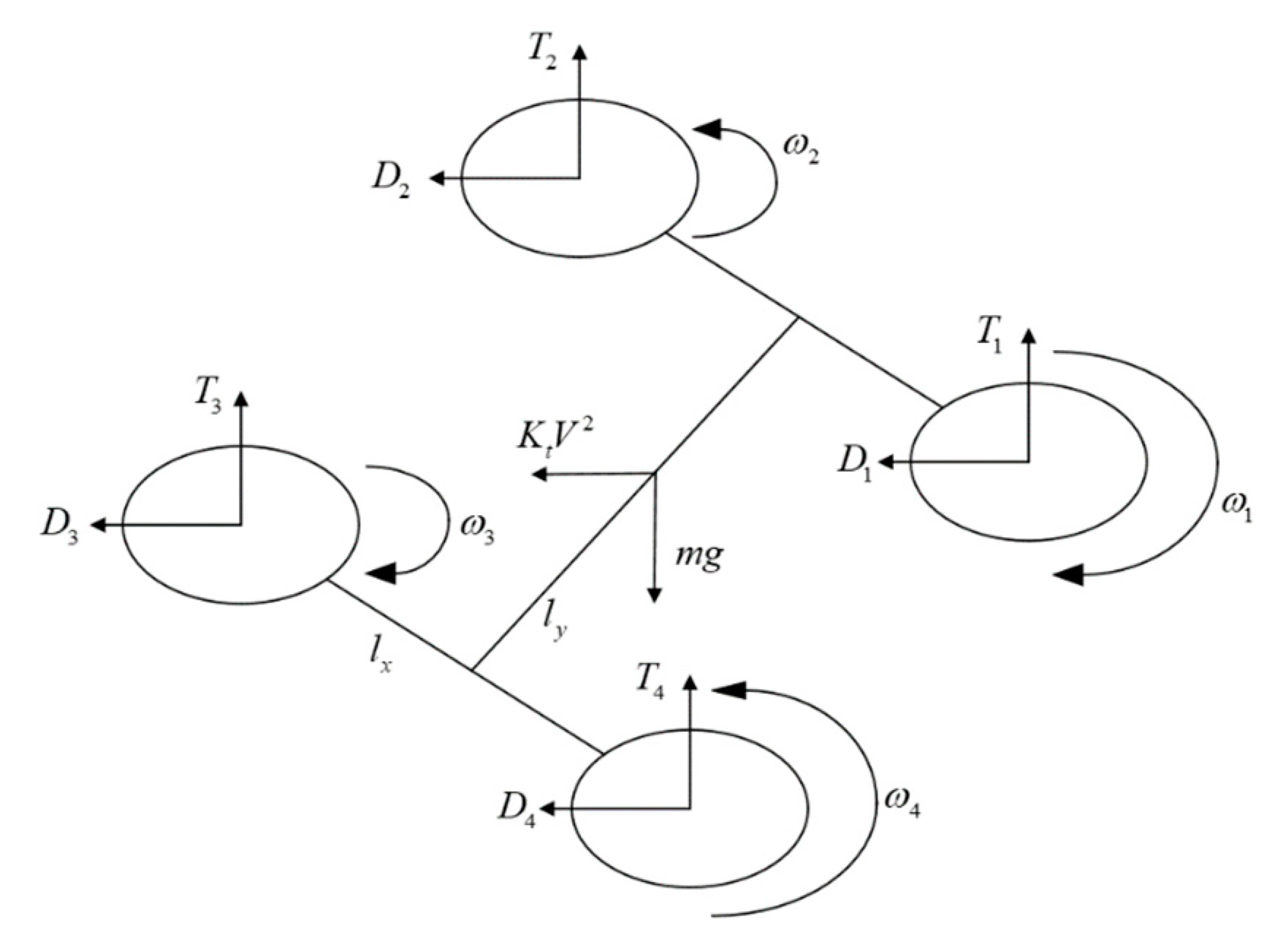
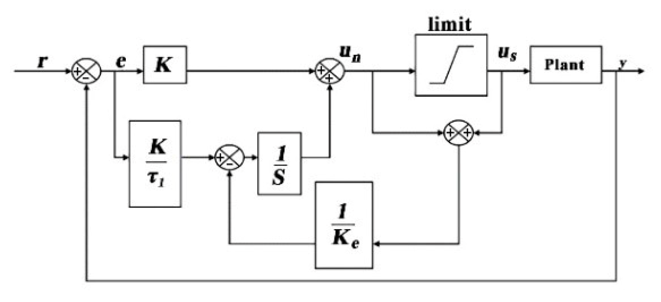
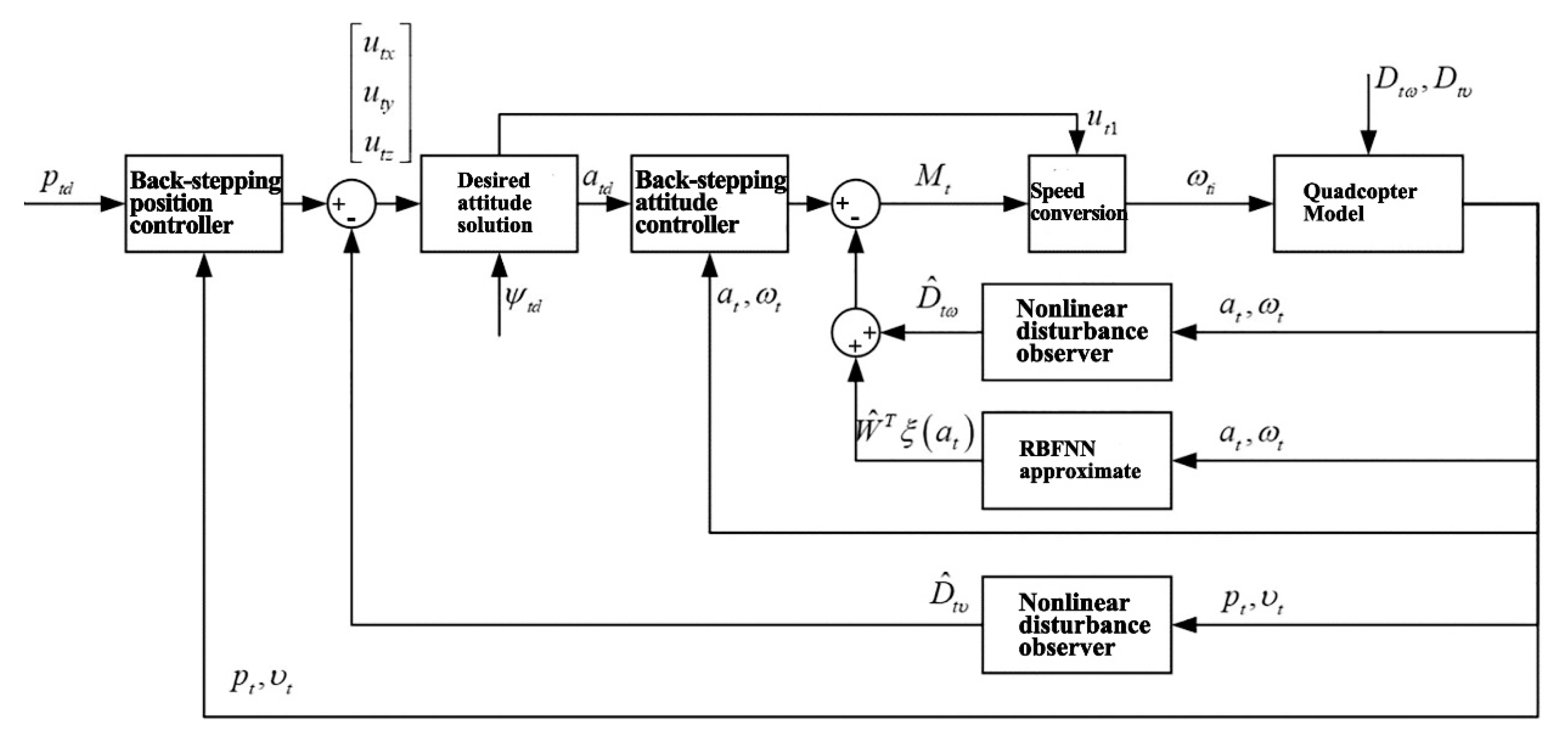
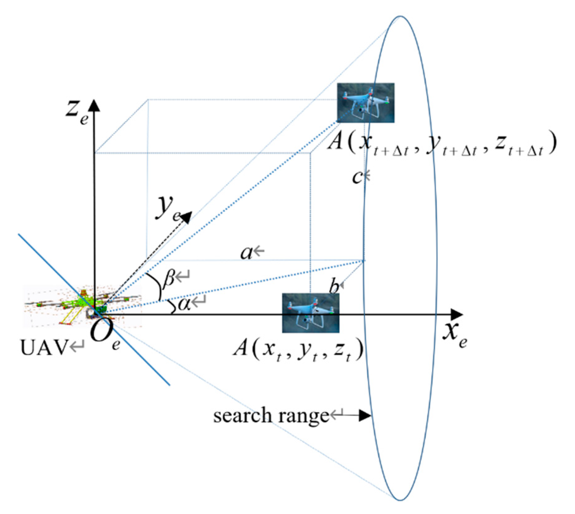
Sensors Free Full Text Design Of Airport Obstacle Free Zone Monitoring Uav System Based On Computer Vision Html

Simple Design For Word Packing List Template List Template Excel

Isolated Receiver Converter Uses Multichannel Opto Isolator

Broadband Telecoms Techneconomyblog
Avant X Programmable 4 Input Distribution Amp From Televes Tv Fool

Sensors Free Full Text Design Of Airport Obstacle Free Zone Monitoring Uav System Based On Computer Vision Html

The Principle Diagram Of Typical Setup Of Iptv Distribution Download Scientific Diagram

Sensors Free Full Text Design Of Airport Obstacle Free Zone Monitoring Uav System Based On Computer Vision Html

Guide On How To Build A Pair Of Diy Floor Standing Speakers With Dual Woofers Http Audiojudgement Com Di Floor Standing Speakers Diy Speakers Speaker Box Diy

Block Diagram Of Trx Download Scientific Diagram

Dtv Receiver Block Diagram Download Scientific Diagram

Pin By Pradeep Singh Tomar On Electronics Products Ku Band Satellites Satellite Antenna

Hinh ảnh Co Lien Quan Subwoofer Box Design Subwoofer Box Audio Amplifier

Sensors Free Full Text Design Of Airport Obstacle Free Zone Monitoring Uav System Based On Computer Vision Html

Block Diagram Of A Satellite Receiver System Download Scientific Diagram

Dtv Receiver Block Diagram Download Scientific Diagram

Uplink Card Block Diagram Download Scientific Diagram